
Note 04
Sacrificial anodes or impressed current?
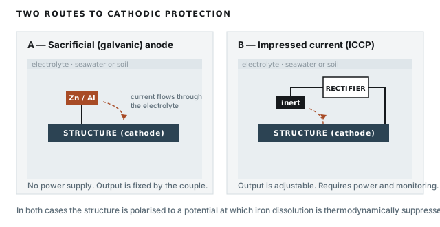
Cathodic protection works by supplying electrons to a structure until its potential is driven low enough that dissolution of iron is no longer favourable. The structure becomes the cathode of a deliberately created cell. There are two ways to supply the current.
The criteria are the same either way
The system is judged on the potential achieved at the structure, not on the current delivered. The criteria in common use are a structure-to-electrolyte potential of −850 mV or more negative against a copper/copper sulphate reference in soil, and −800 mV or more negative against a silver/silver chloride reference in seawater. For structures in anaerobic conditions with sulphate-reducing bacteria, a more negative criterion of −950 mV is normally applied.
There is also an upper limit. Polarising a coated structure more negative than about −1100 mV generates hydrogen at the surface, which disbonds coatings and, on high-strength steels, risks embrittlement. Over-protection is a real failure mode, not a theoretical one, and it is a risk that belongs almost entirely to impressed current systems.
Sacrificial anodes
A more anodic metal is connected to the structure and consumed. Zinc, aluminium alloys and magnesium are the practical choices, with open-circuit potentials of roughly −1.05 V, −1.10 V and −1.5 to −1.7 V against silver/silver chloride respectively.
The driving voltage is fixed by the couple and is small — a few hundred millivolts. That constrains the system in two ways. Current output is limited, so the structure must be well coated for the demand to be met. And current will not travel far in a resistive electrolyte, so anodes must be distributed close to what they protect. Magnesium is used in soil precisely because its higher driving voltage overcomes higher resistivity, at the cost of much faster consumption.
What you get in exchange is a system with no power supply, no cabling, no switchgear, nothing to adjust and nothing to interfere with neighbouring structures. It cannot be turned off, and it cannot be turned up.
Impressed current
A rectifier drives current from inert or semi-inert anodes to the structure. The driving voltage is whatever the rectifier is set to, so current demand is essentially not a constraint, and large or poorly coated structures become protectable.
The costs are operational rather than material. The system needs a power supply, it needs monitoring, and it needs someone competent to interpret the readings and adjust the output. An incorrectly set rectifier will over-protect and disbond the coating it was installed to support. Current discharged from an impressed current system can also pick up on nearby buried structures and cause interference corrosion where it leaves them, which is why interference testing is part of commissioning rather than an optional extra.
| Sacrificial | Impressed current | |
|---|---|---|
| Driving voltage | Fixed, a few hundred mV | Adjustable, tens of volts |
| Current capacity | Limited | Effectively unlimited |
| Suits | Well-coated, smaller structures; low-resistivity electrolyte | Large or bare structures; high-resistivity soil |
| Power required | None | Continuous |
| Over-protection risk | Very low | Real, requires control |
| Interference risk | Low | Requires assessment |
| Main operating cost | Anode replacement | Power, survey, maintenance |
The decision, in practice
Estimate the current demand from the exposed area and the coating breakdown factor assumed over the design life. If a reasonable number of anodes can supply it in the electrolyte resistivity you actually have, use sacrificial anodes — the system will need less attention over its life and will fail gracefully rather than suddenly. If they cannot, or if the structure is too large, too bare, or in soil too resistive, use impressed current and budget for the monitoring that goes with it.
Cathodic protection does not replace coating. The two are designed together. The coating does the bulk of the work and the cathodic protection handles the defects. A system sized on the assumption of a good coating, applied over a poor one, will run out of anode long before the design life.
Download this note as a PDF for circulation or filing.
Standards and further reading
- ISO 15589-1 — Cathodic protection of pipeline systems: on-land pipelines.
- EN 12473 — General principles of cathodic protection in seawater.
- EN 12474 — Cathodic protection of submarine pipelines.
- NACE SP0169 — Control of external corrosion on underground or submerged metallic piping systems.
- DNV-RP-B401 — Cathodic protection design.